Mini Pro Assembly Instructions
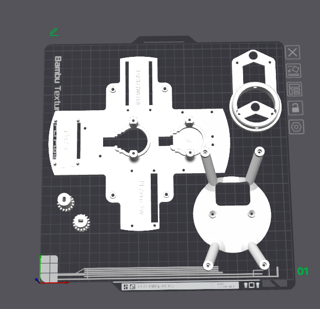
Printing Instructions
- Everything can be printed out of PLA. If you prefer, you can print the gears with PETG, but avoid mixing and matching materials for moving parts (e.g., a radial arm in PLA, a spur gear in PETG).
- Save the magnet cup and the sand bed for last because you may have to scale this part to fit your particular setup.
- Print the acrylic holder and test fit for your bowl. I've seen reports of varying sizes for the bowl. If yours don't fit, try a different size from the Patreon page. If you still cannot find a good fit, message me on Discord and I'd love to make adjustments for you.
- If you're in Europe, you'd have to print the 250mm OD version for the acrylic holder (I heard that it's hard to find 10-inch acrylic over there).
- If you have a printer bed bigger than 256mm³, you can also print the acrylic holder in 1 piece.
28BYJ-48 Version
For the 28BYJ-48 version, print these parts differently. The rest of the parts use the standard files.
Assembly Instructions
- Start by assembling the electronics and make sure that everything works before mounting them in the bowl.
- Test fit your bearing to the motor holder and the big angular gear. If needed, add threaded inserts and use M3 set screws (or short screws).
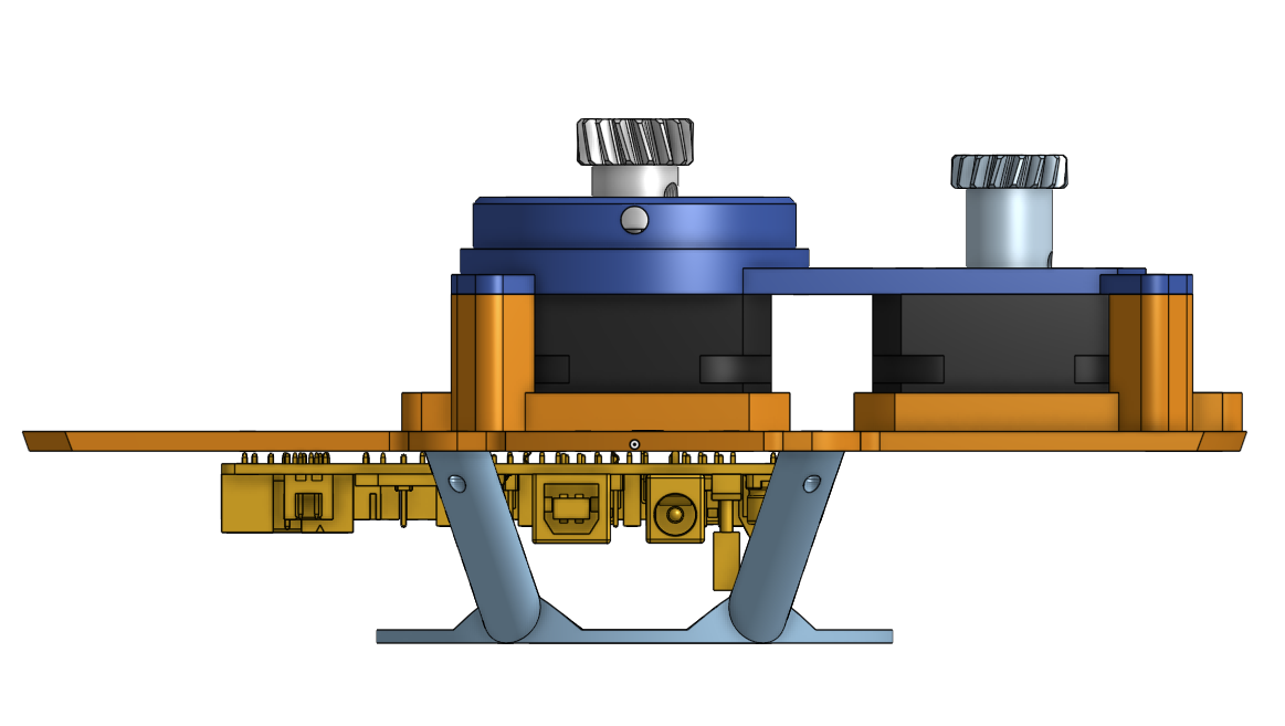
- Attach the motor wires, sit the two motors in their slots (label the wires so you know what cable is for what axis). Add the motor holder and secure it with 4 M3 screws (corners). You can also secure the motor to the holder, but it's optional.
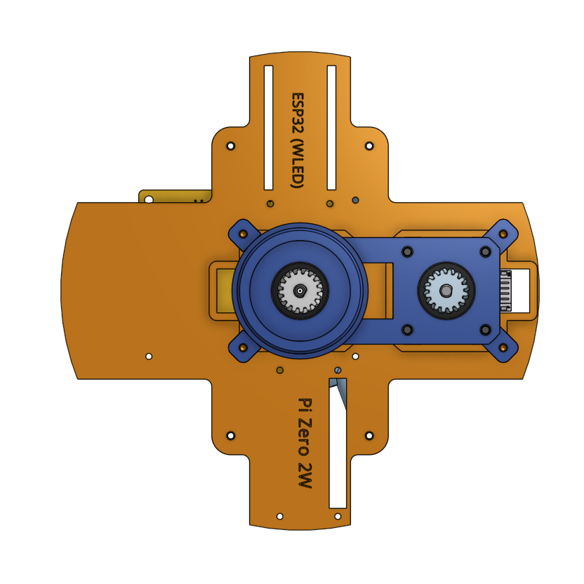
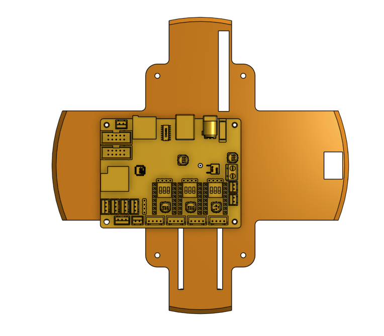
- Flip the motor base around and secure the DLC32 to the motor base using 3 M3 screws. The orientation should match as follows.
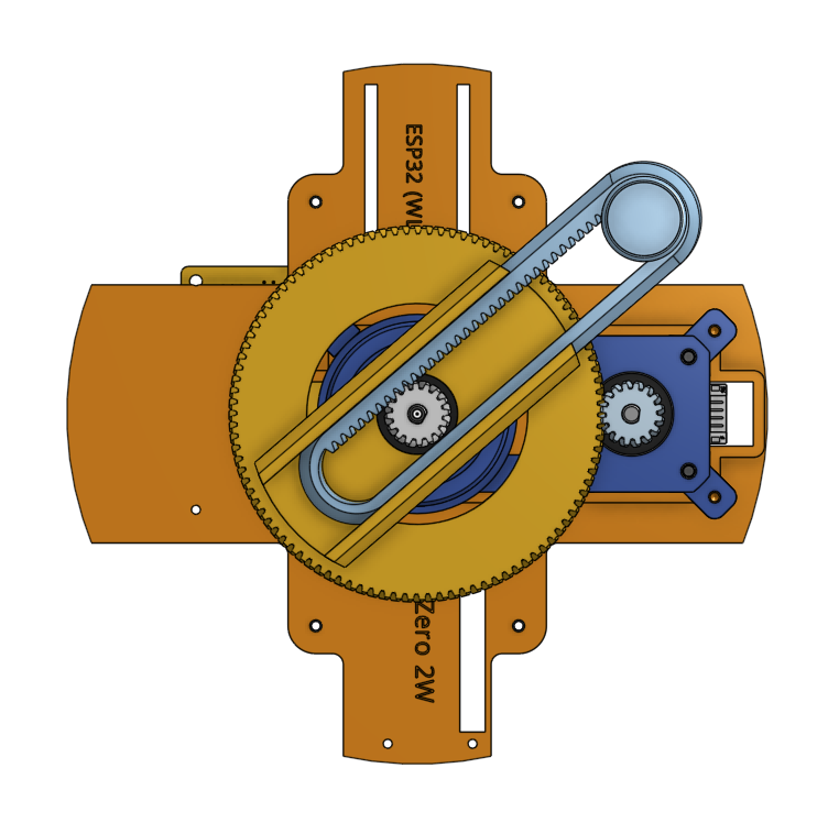
- Add the Pi Zero 2W and wire them to the DLC32. If you still use WLED (not recommended anymore; check out DW LEDs), attach the ESP32 as well. After that, secure the Pi and the ESP32 to the base using M3 screws.
- If you have a USB-a to micro USB adapter, simply skip this step and plug the dlc32 into the pi (not the power port). If not you can set up UART over pins. There are some additional steps as outlined in Deploying Backend.
- Set the 3 switches under the motor drivers to off for both axes.
- Adjust Vref values using the instructions in Setting VREF.
- Add connector for the LED. Make sure the radial arm does not get caught with anything.


- Secure the base to the base holder with M3 screws.
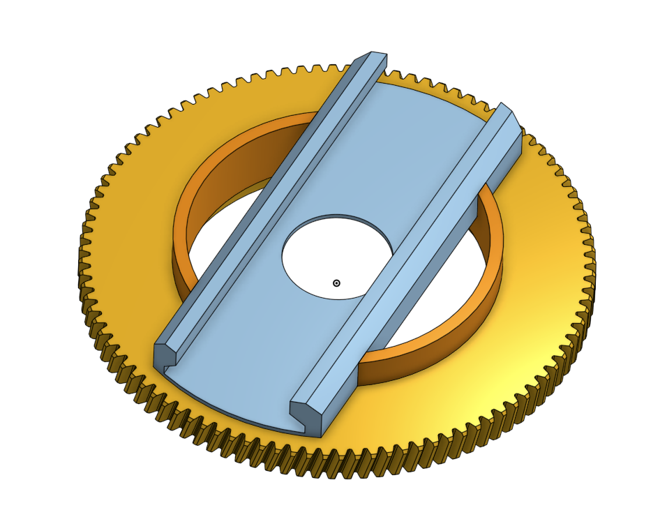
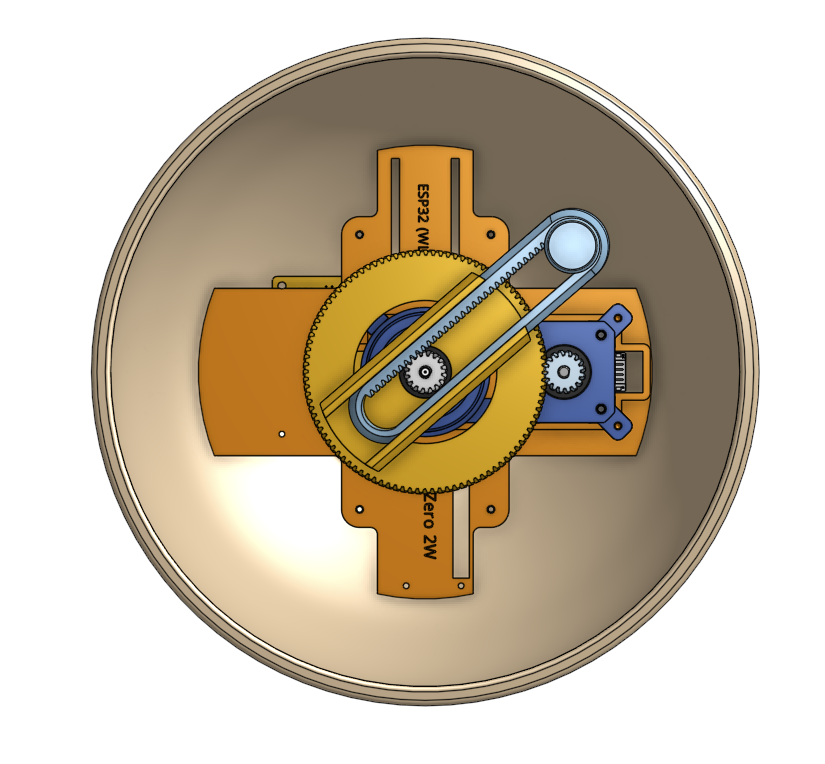
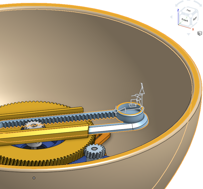
- Assemble the angular gear like this. Depending on the fit, you may want to add some glue so the radial arm won't rotate around.
- Add the angular gear, radial arm and two spur gears (the longer one in the center).
- Add the LED strip to the sand bed. You should have a connector here so you can easily take off the base. LED strips usually come with both female and male connectors. On the other end, you can use a heat-shrink tube or your preferred method to connect to the DuPont wires.
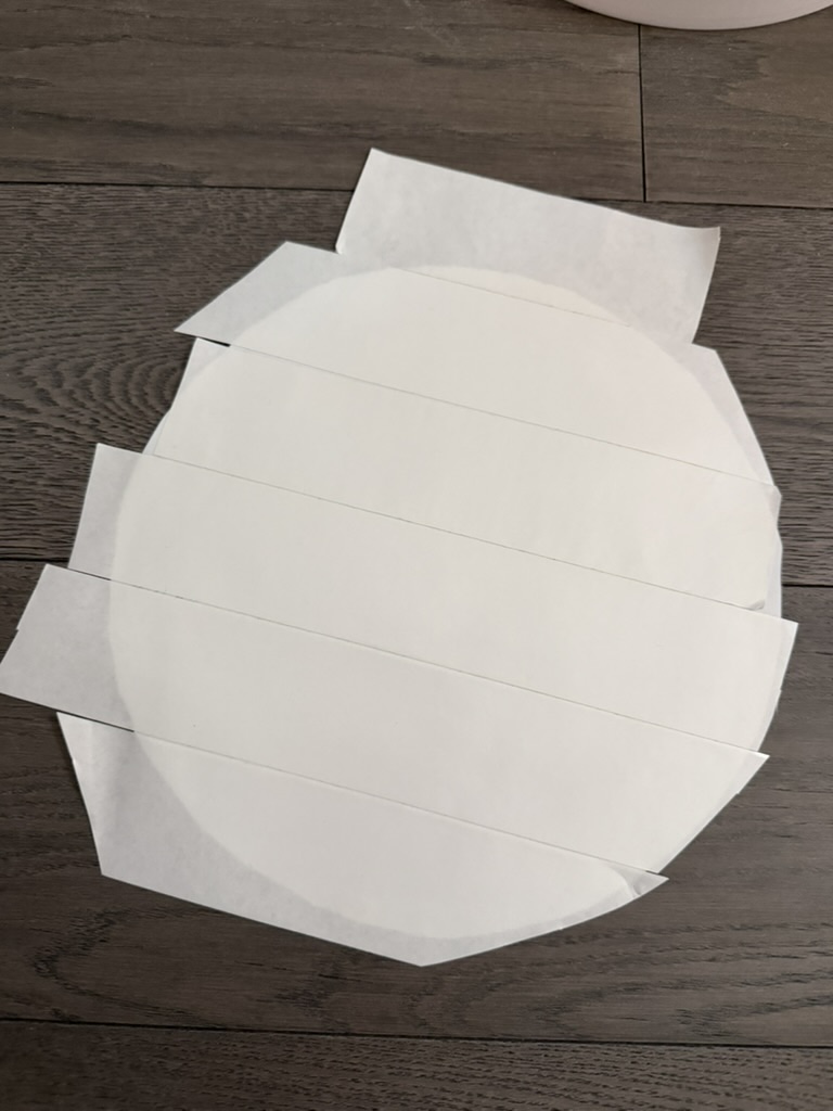
- Add the Eva foam to the sand bed, secure it in place using double-sided tape. Don't overlap any tape sections.
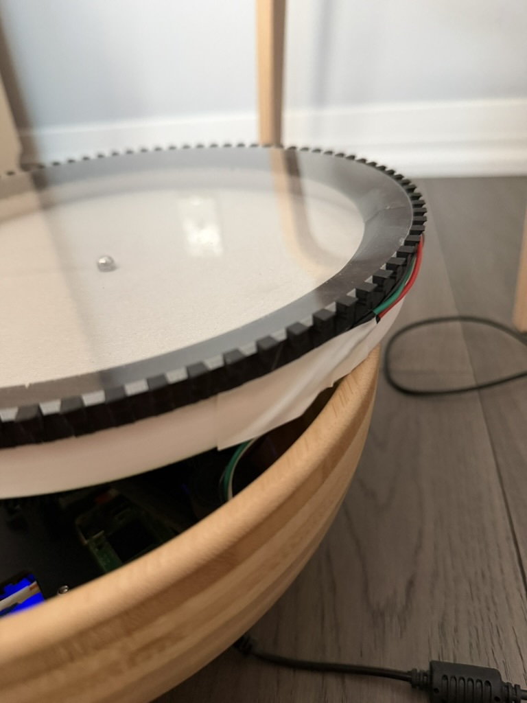
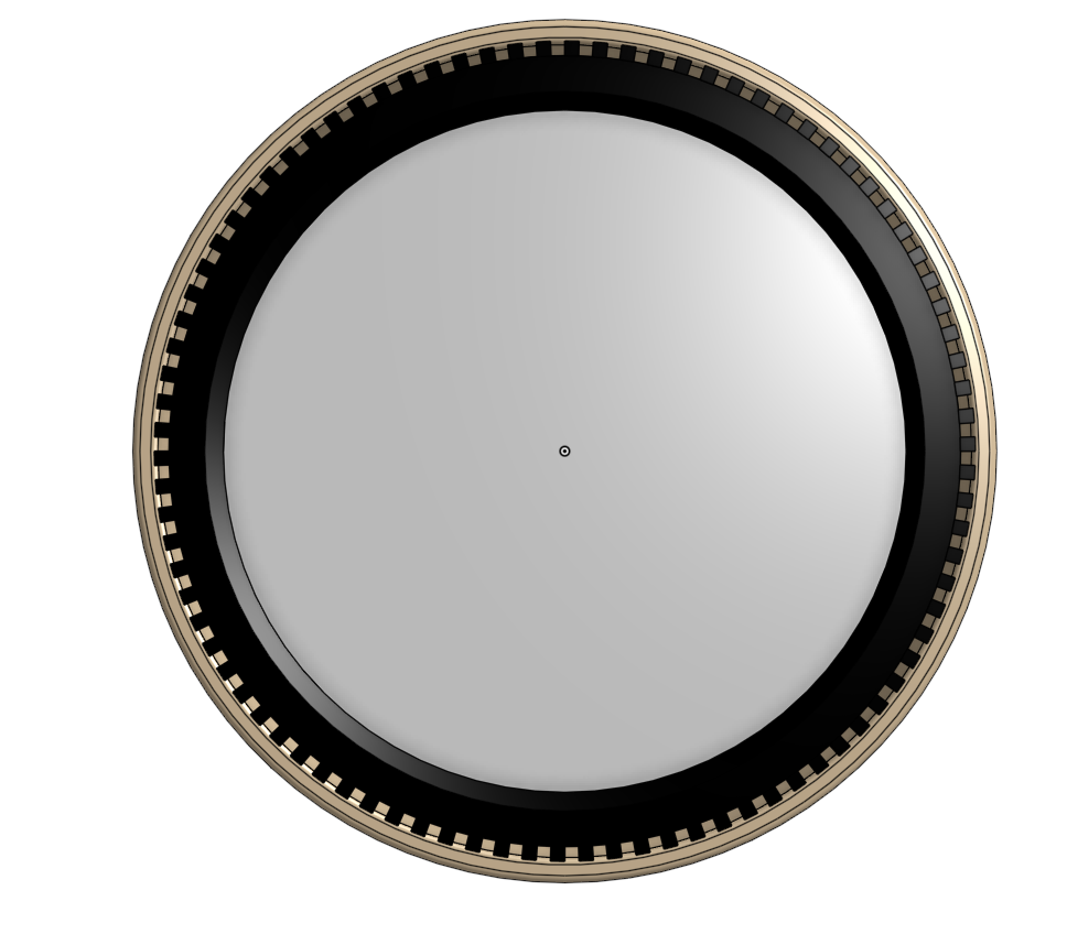
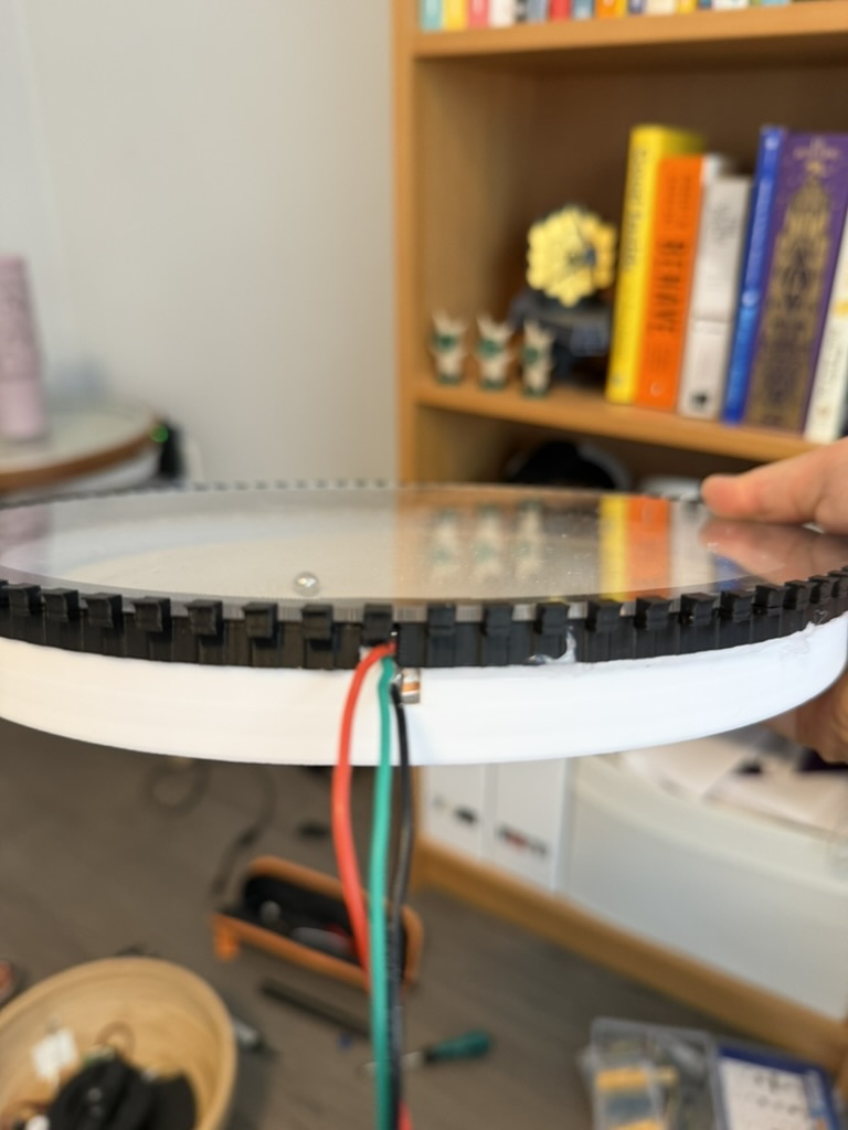
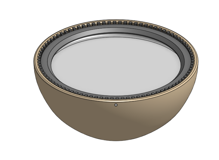
- Test fit your two pieces of acrylic holder to the top of the wooden bowl first. The ring should sit flush with the top of the bowl. Next, add the acrylic in place. Everything should fit nicely. Please reach out to me in Discord if you have any problems and I can provide some adjustments.
- Glue (hot or instant) the acrylic holder to the sand bed. If your acrylic holder is printed in two segments, use electrical tape (preferably on the underside) to prevent light leak. You may also want to add some super glue to secure the electrical tape in place.
- Cut out a small section of the acrylic holder for the LED wires to come through.
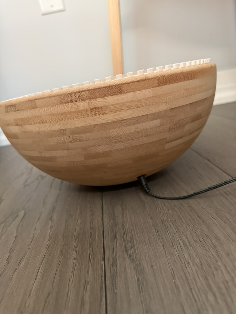
- Drill a hole through the wooden base and add a female-to-male DC cable. Make sure that the power cable can connect fully and there's current. Secure the female side with hot glue.


- Use the drill template as a guide at the bottom (thanks, Bill, for the idea), drill two holes to secure the base in place. You can also use thin two-sided tape or other adhesive here. Please be mindful that we don't have a lot of clearance height. Use M3 or M4 10mm wood screws to secure the base holder to the bowl. Make sure that the base holder is level with the bottom of the bowl.
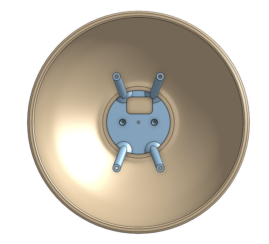
- Add the motor assembly and secure in place.
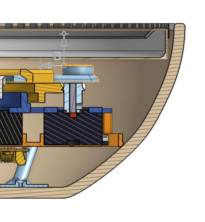
- Now, you want to measure the distance from the top of the magnet ring to the top of the bowl in various places (center, fully extended in the four posts' directions). If there are too many discrepancies here, you may have got yourself a bowl with an uneven bottom. Adding a couple of washers in some of the posts may help.
- The distance in the model is 30.4mm. The height of the sand bed + acrylic holder is 25.75, leaving us a gap of 4.65mm (from the top of the magnet cup to the bottom of the sand bed). The magnet cup depth is 6mm; therefore, we should have the magnet adapter of 6mm + 4.65mm - 1mm (tolerance) = 9.65mm. You'd want to swap out 4.65 with your smallest gap measured above to make sure we have enough clearance. You can then scale the height of the adapter in your slicer.
- Once I receive enough feedback here, I can standardize a couple of adapter sizes and include them in the model.
- The sand bed is thin enough that you can use a steel ball here instead of a magnet ball. Make sure that you don't use a ring magnet because the steel ball can be off-center. You also don't need to use big magnets like the DWP. I actually use 3 5x3mm magnets, and they work great.
- Once the adapter is printed, add it to the magnet cup, add the sand bed + acrylic holder, sand, magnet ball or steel ball, and acrylic. Enjoy the DWMP!
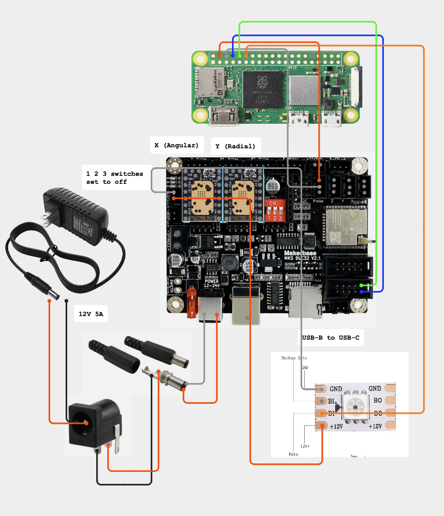
Wiring
- If you have a USB-a to micro USB adapter, simply skip the blue and green wires and plug the dlc32 into the pi (not the power port). If not you can set up UART over pins. There are some additional steps as outlined in Deploying Backend.
28BYJ-48 Wiring
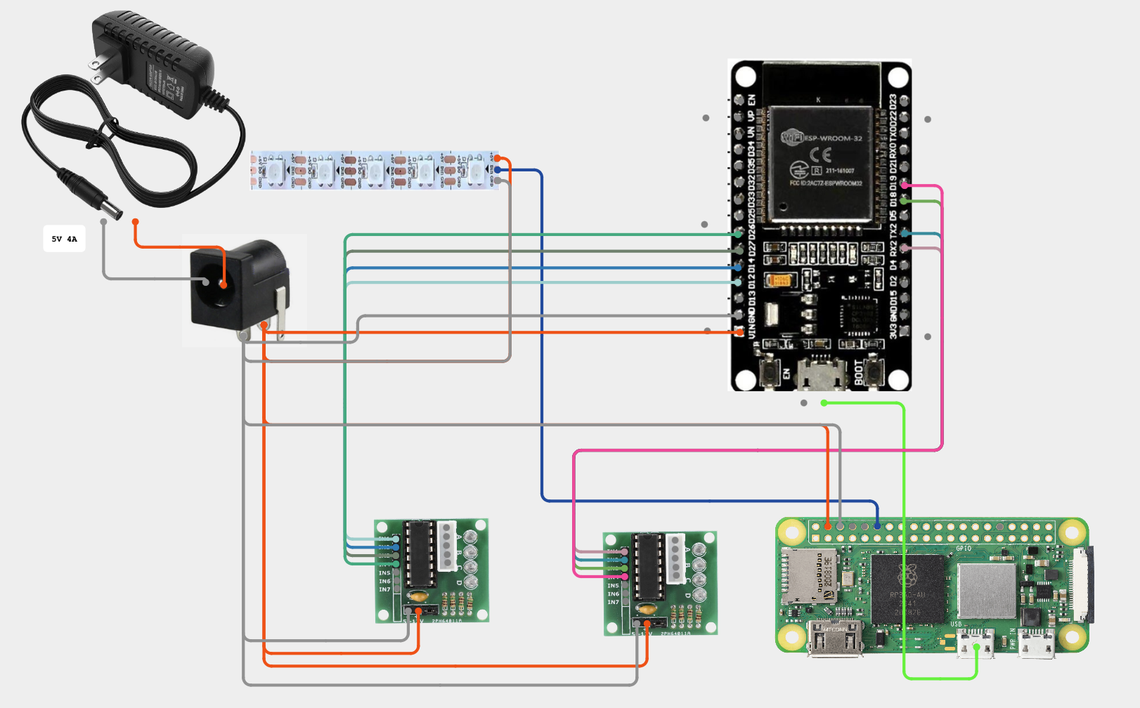
- Wiring for the 28BYJ-48 is tricky because we have to supply power to 5 components. If you have some lying around, it's recommended to use two five-way Wago connectors for this. If not, you can always bundle the wires together. Use heat sink tube and/or solder to secure the connection.
- For the Dupont jumpers, these tend to loosen up the more you connect and disconnect them, so avoid doing that. Use hot glue to secure the connection if needed.
- For the motor signal wires, if you need to change direction, you should do that in the firmware file instead of physically moving the wires.
Additional Resources
Join our Discord community for additional support during assembly at https://discord.gg/YZ8PTezVHt.