Dune Weaver Pro Assembly Instructions
Assembly Steps
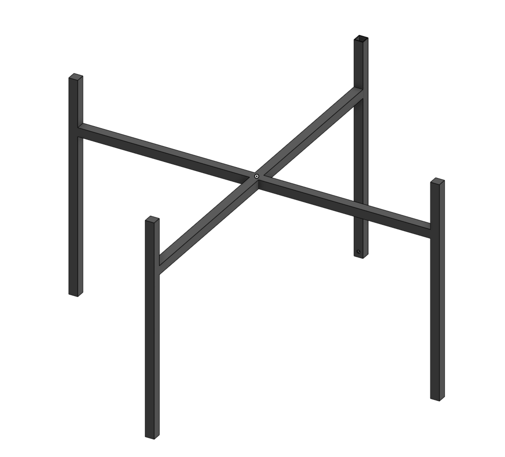
- Assemble the IKEA leg upside down
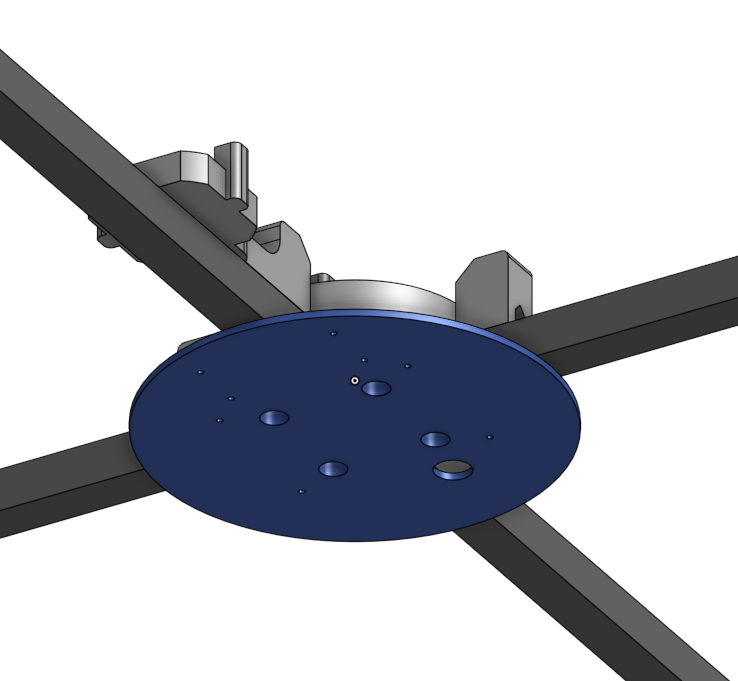
- Add the base and secure the base aligner underneath with 4 M4x15mm self-tapping wood screws

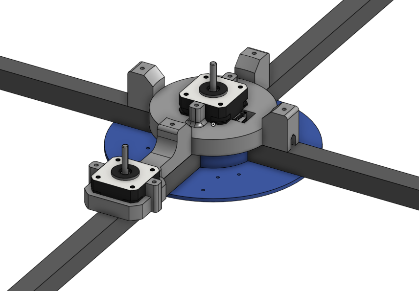
- Connect the motor cable, add the motors and secure the motors to the holder with 4 M3x10mm machine screw for each motor. Secure the motor with the aligner to the base with 2 M4x15mm self-tapping wood screws for each motor.
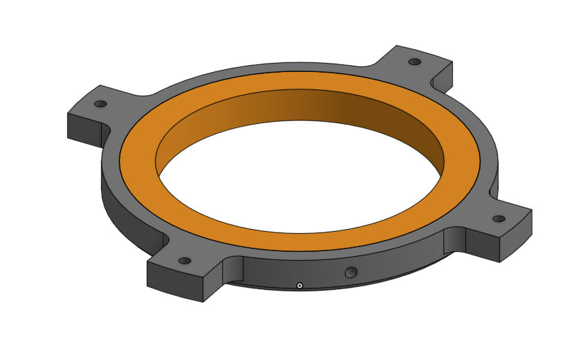
- Add the bearing to the outer bearing holder. Secure with M4 set screws or scale the model for a tight press fit. You can also use a dab of glue to hold the bearing in place.
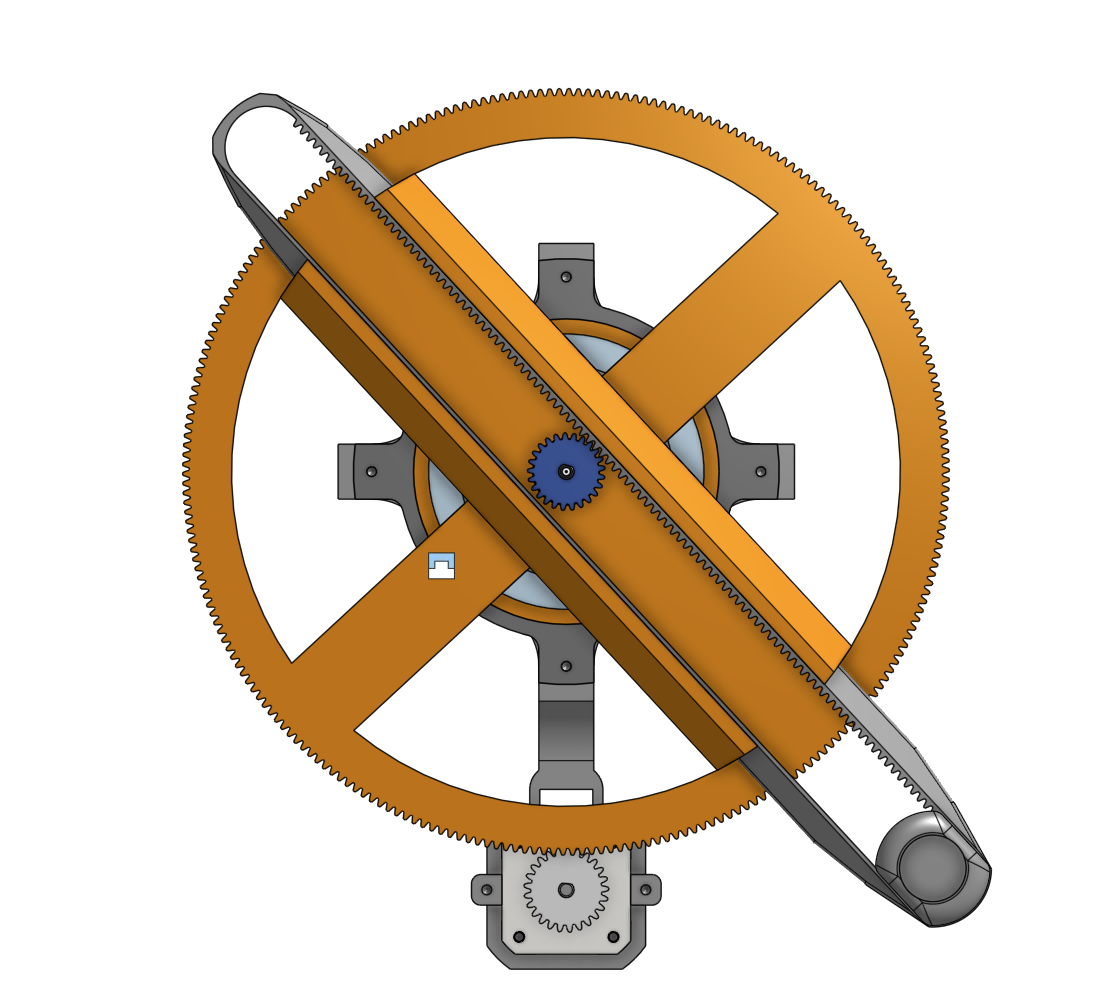
- Add the inner bearing to the angular gear and glue it in place. Wait for the glue to completely dry.
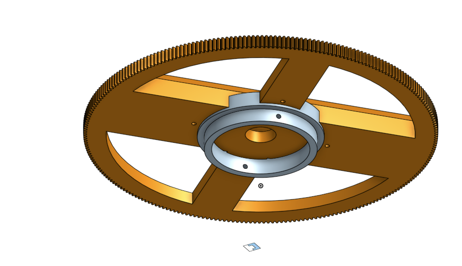
- Press fit the angular gear to the bearing. Add set screws or glue to secure it in place. Make sure that the inner bearing moves when the angular gear moves.
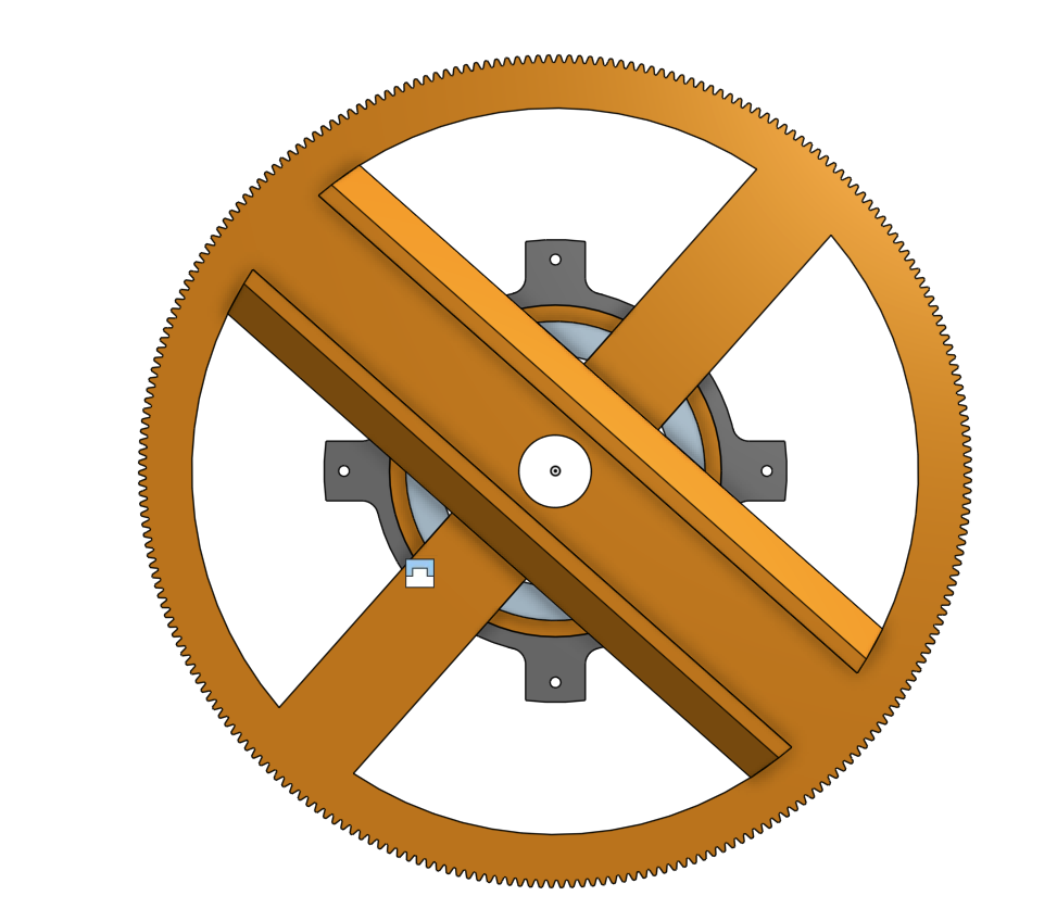
- Add the assembly to the base and secure with 4 M4x15mm self tapping screws.
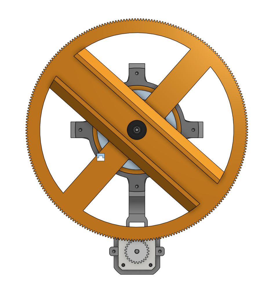
- Add the radial arm and the inner spur gear
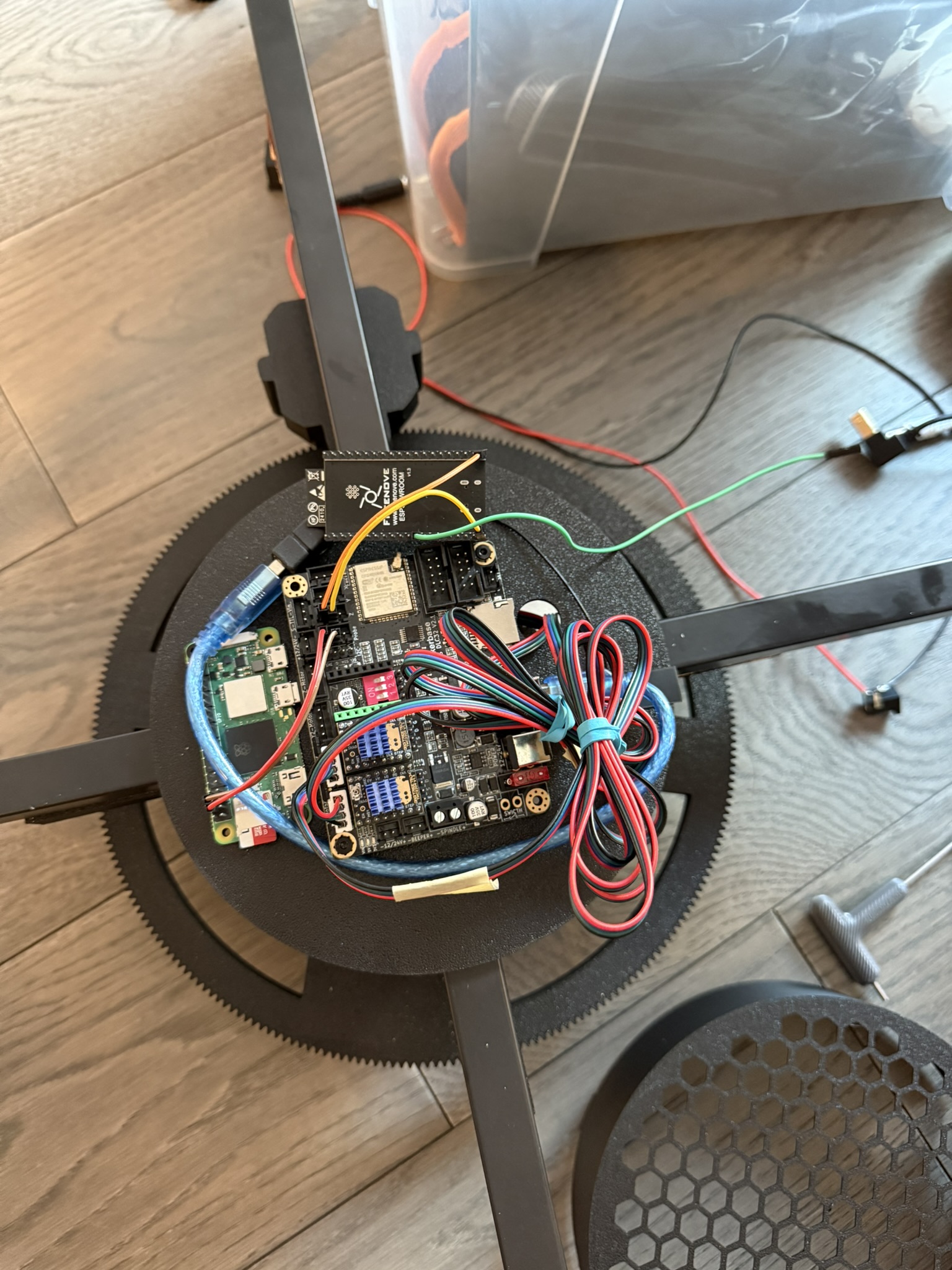
- Secure the Raspberry Pi 2W (with usb cabled attached). Then secure the dlc32 board on top of the usb cable. Test electronics before proceeding with wiring.
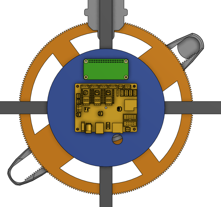
- After completing wiring, install the electronics cover
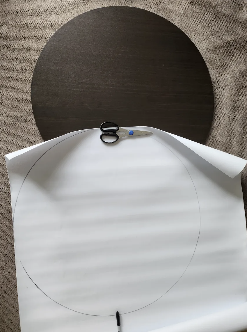
- Trace and cut out the EVA to the shape of the wooden base. Add minimal glue if EVA foam curls.
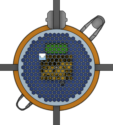
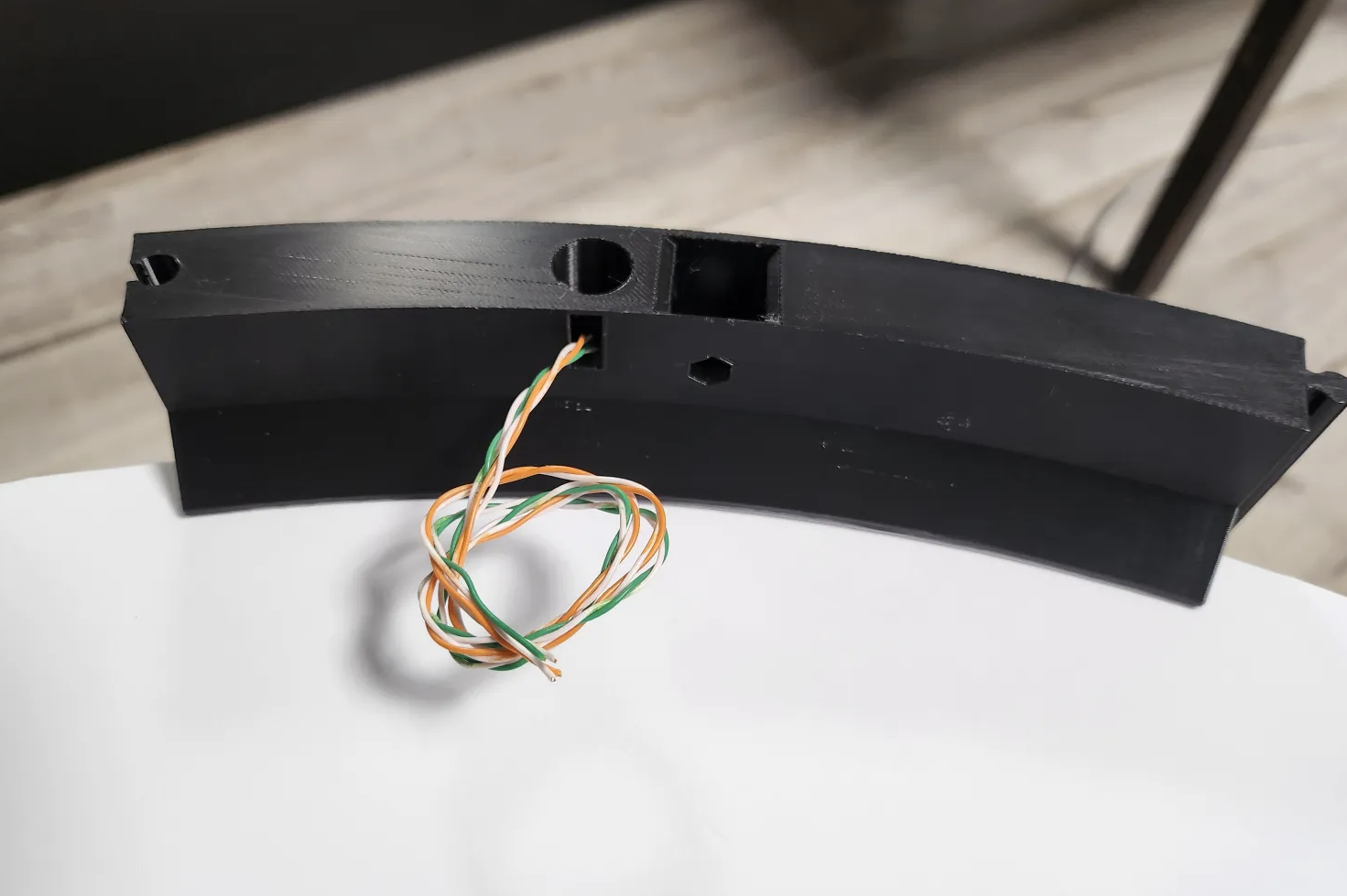
- Add the led wires
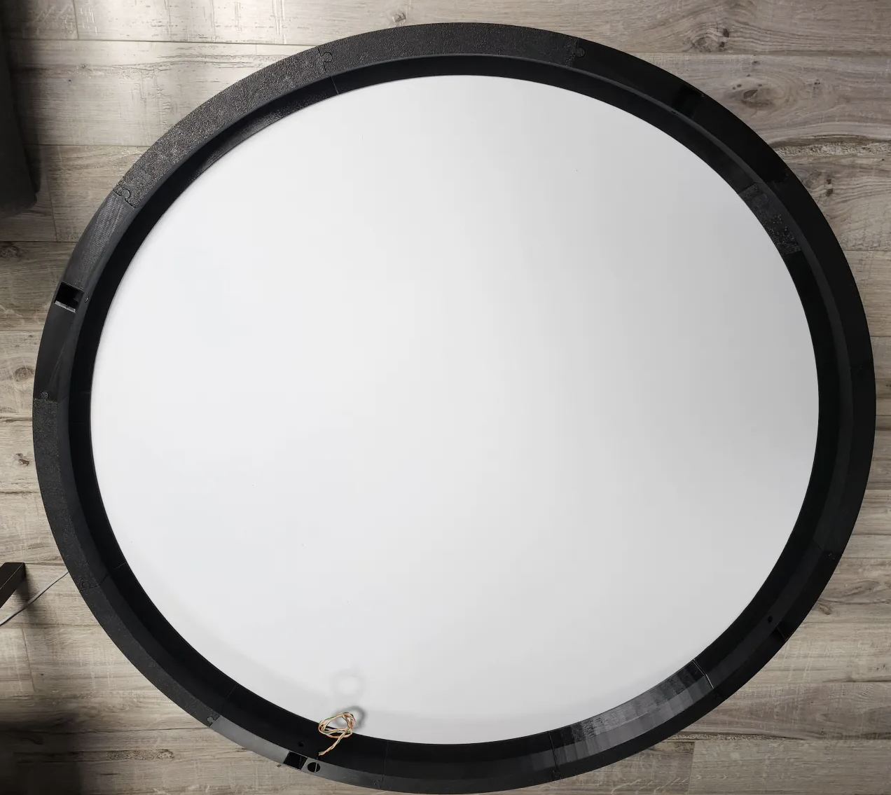
- Assemble the enclosure around the wooden sand bed


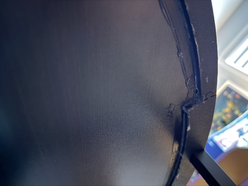
- Optional: Caulk the bottom of the sand bed to prevent sand from escaping
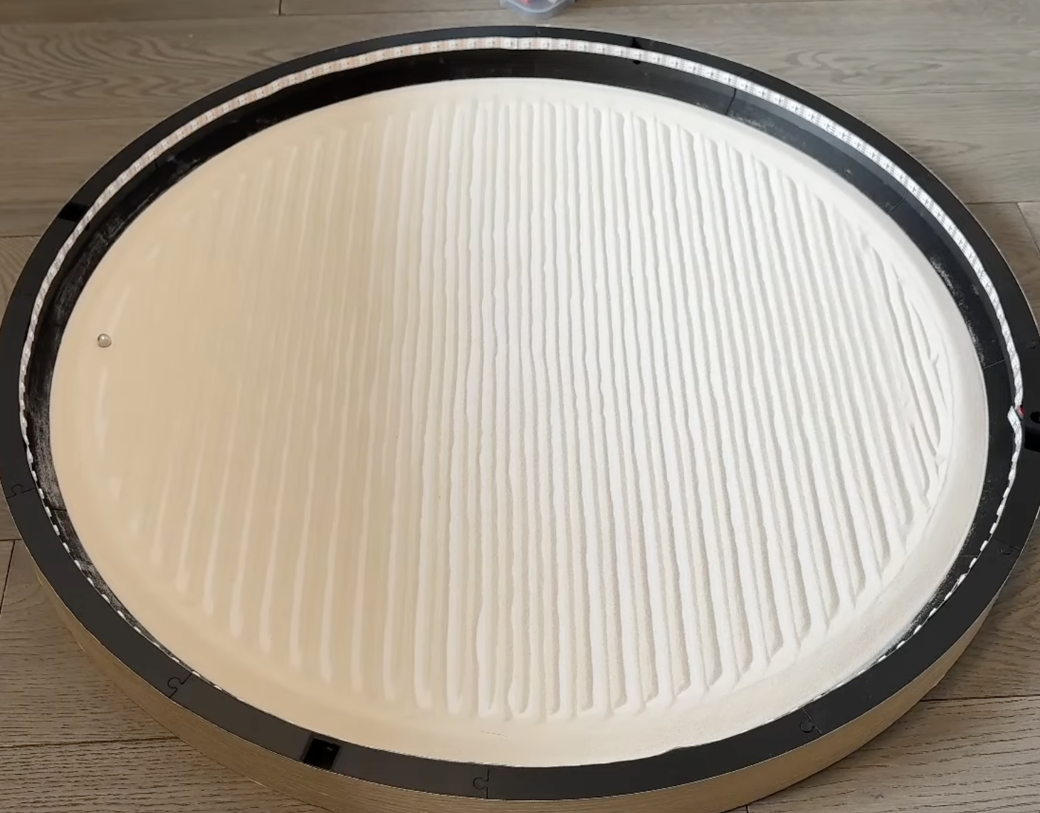
- Add approximately 1.4kg of sand and the magnetic ball. Sand should cover about 25% of the magnetic ball height. Install the LEDs and solder connections.
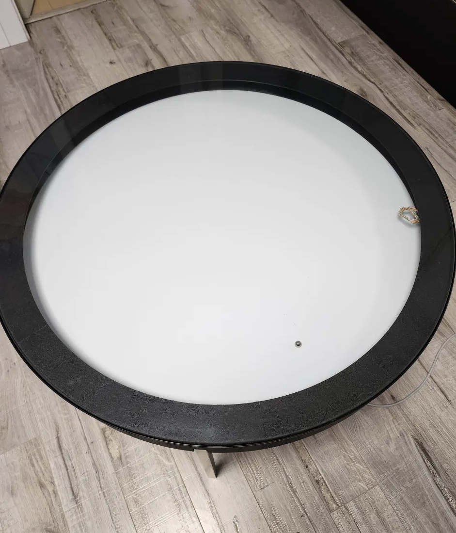
- Add the LED cover to the glass and put the glass ring on

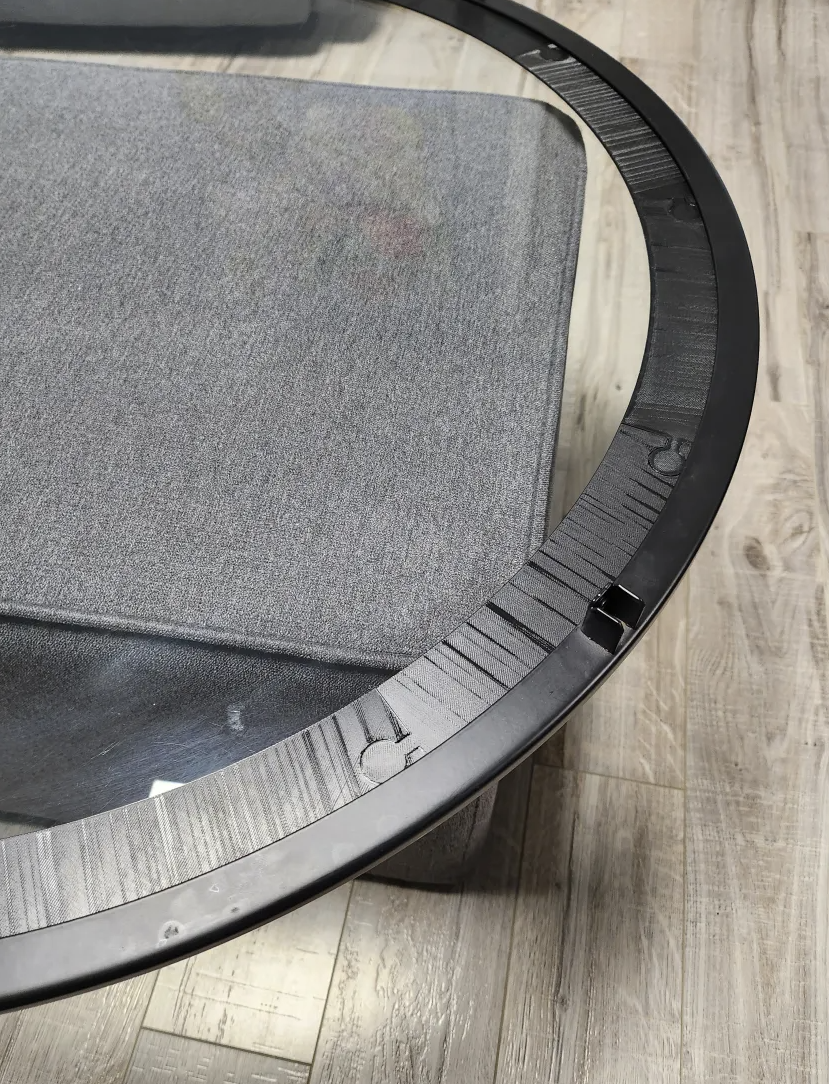
- Put the sand bed on the four legs. Add the glass ring with the glass on top
Wiring
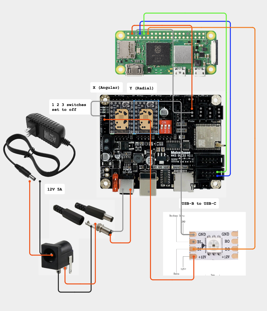
Pi Zero 2W and DLC32 Connection
-
Add the Pi Zero 2W and wire to the DLC32. If using WLED (deprecated; use DW LEDs instead), attach ESP32 as well.
-
USB Connection Options:
- Use USB-a to micro USB adapter to connect dlc32 to Pi (skip next step)
- Alternatively, set up UART over pins following additional instructions
-
Set the 3 switches under the motor drivers to off for both axes
-
Adjust Vref values using the provided instructions.
Power Supply
- Single 12V 5A supply powers everything
- Current requirements depend on LED choice
- Example: 12V WS2815 60 LEDs/m
- Higher LED density may require increased current capacity
Connection Notes
- Use Dupont wires for Pi Zero 2W and ESP32 board (prone to issues; consider soldering after testing)
- Confirm all electronics function before final assembly
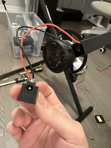
Power Cable Installation
- Connect power cable to female 12V plug
- Run power wires through the steel tube
LED Wiring
- Create connector plug for LED removal when detaching table top
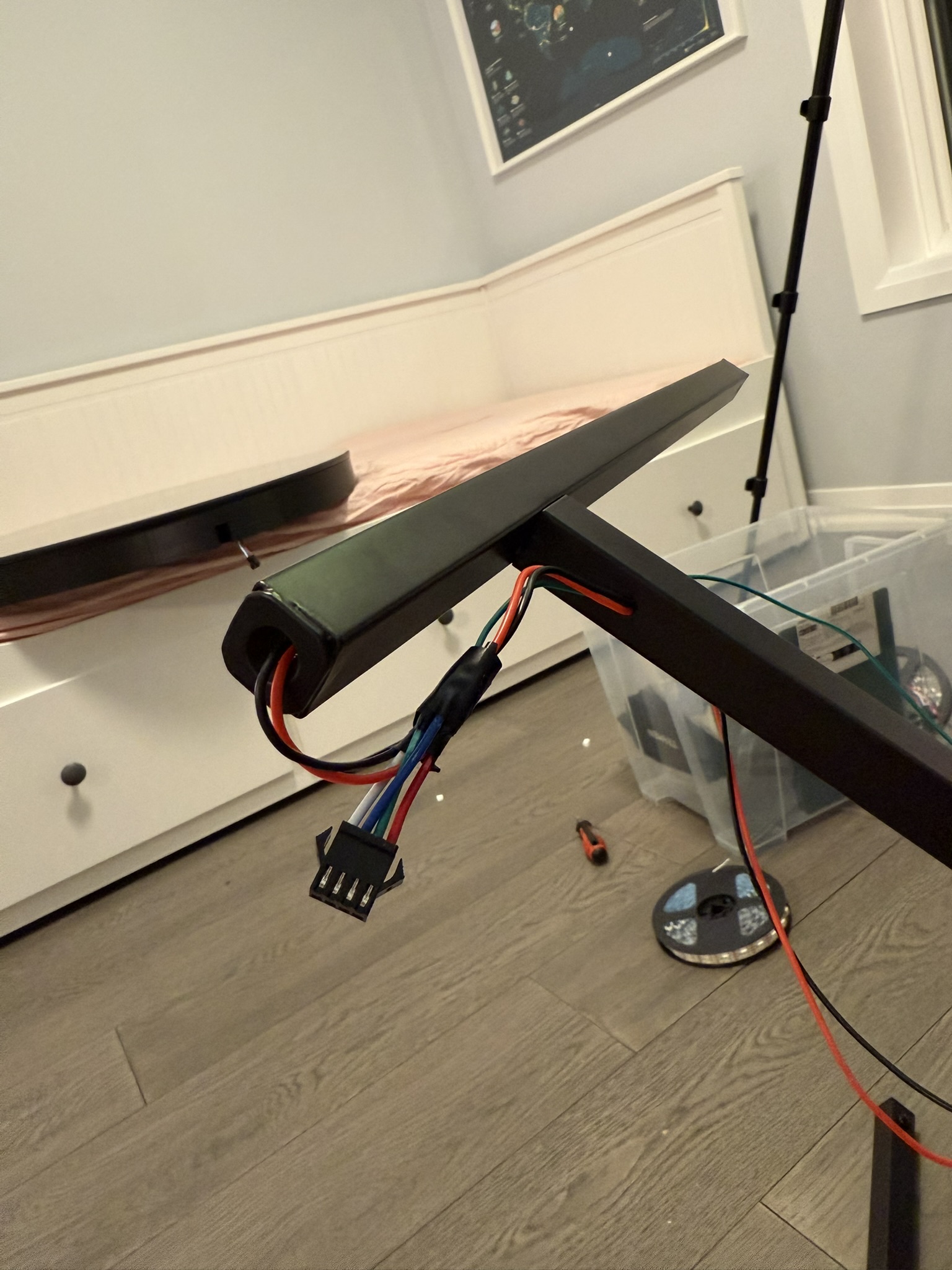
- Green cable = data cable (connects to pin 16 on ESP32)